
If you are looking into pogo pins for your application, sooner or later you will ask which mounting options are available. This article goes through the different options, explains their advantages and disadvantages, and gives some general advice. If you have further questions after reading, please contact us directly.
Our engineers are experts in all sorts of connectors, and our experience with over 6,000 custom connector designs helps you avoid costly mistakes. Besides your structural design, we will also recommend a mounting method that fits your product cost.
How to mount pogo pin connectors via SMT (Options 1–4)
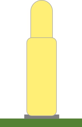
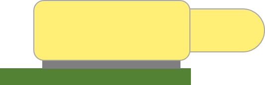
Option 1: Solder paste on a solder pad
The first and simplest way is to place the connector on a solder pad and fix it with solder paste. While this is certainly the easiest way, we usually do not recommend it. It generally isn’t very stable, and pins may break away or dislocate through vibration or mating pressure.
Option 2: Pins with plug-in tails
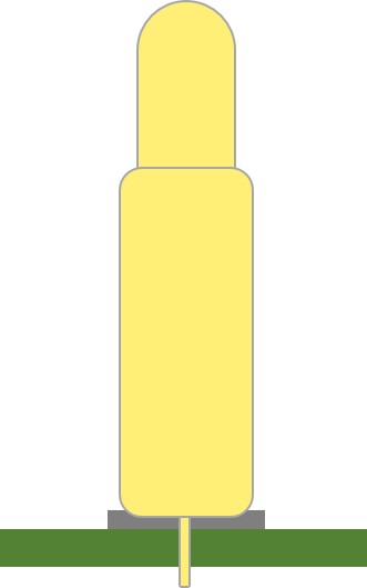
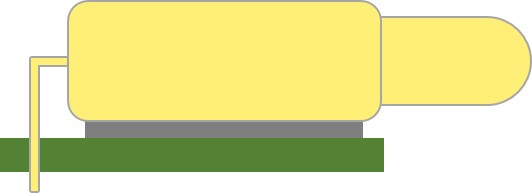
The second option is to use a pogo pin with a plug-in tail that goes through a mounting hole on the PCB, as is common practice for most larger components. The tail gives the pin additional support and increases stability.
Option 3: Housing with mounting legs
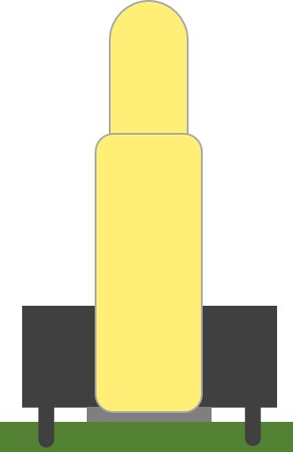
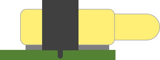
The third option is to use a housing with legs to mount the whole connector securely on the board, while the pogo pins are simply mounted on a gold pad by pressure or solder paste (as in Option 1). This version is stable enough for most applications.
Option 4: Housing and pins with plug-in tails
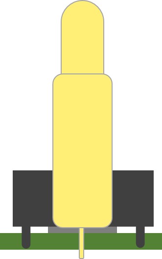
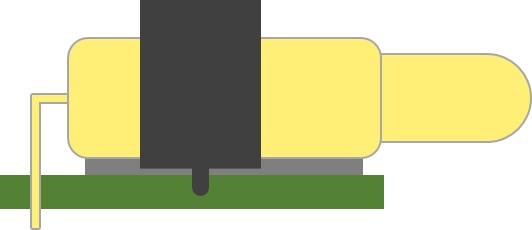
This combines Options 2 and 3: both the housing and the pins have plug-in tails. It is a very secure way of mounting a connector and gives the most stable and durable connection. We recommend this type of mounting whenever possible.
What to pay attention to when using SMT with pogo pin connectors?
Like most other components, pogo pins are heat resistant only up to a certain point. Standard housing and spring materials may not withstand the heat, or can only go through the reflow soldering process once. If you plan several reflow cycles, let us know. We will choose the right pins and materials for your requirements to avoid malfunctions at a later stage.
How to design the PCB footprint for DIP-type pogo pin connectors?
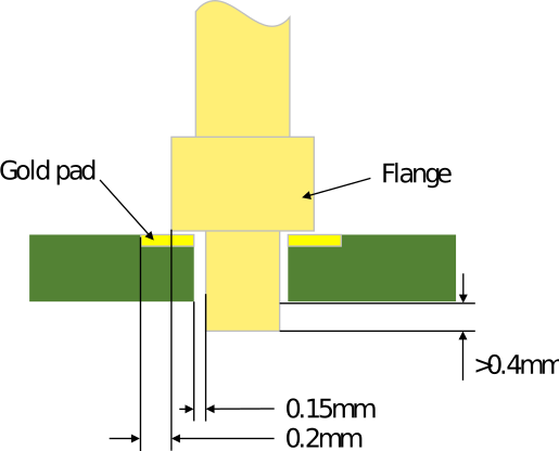
As a rule of thumb, the hole in the PCB should have a radius of “pogo pin tail + 0.3 mm”. The soldering gold pad should generally have a radius of “flange + 0.4 mm”. The tail itself should be at least “PCB thickness + 0.4 mm” long. These numbers may vary at smaller pitches and also depend on the tolerances your EMS provider works with.
How to design the FPC footprint for pogo pin connectors?
For flex PCBs the rules are similar to normal PCBs. Only the tail of the pin should be “FPC thickness + 0.1 mm”.
How to design the PCB for SMT-mounted pogo pin connectors?
The soldering pads should be “pogo pin radius + 0.5 mm”.
Option 5: How to mount pogo pins with a cable?
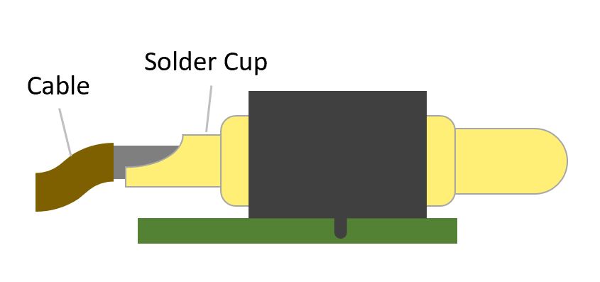
Pogo pins can be connected to the PCB via a cable. For this purpose, the pogo pin gets a small solder cup at the back, which is used to attach the cable. C.C.P. Contact Probes Co., Ltd. can supply single pins or complete connectors with preassembled cables. Standard or non-standard connectors, such as USB connectors or machined pins, can also be added to the other end of the cable.
Option 6: How to mount pogo pins via spring tails?
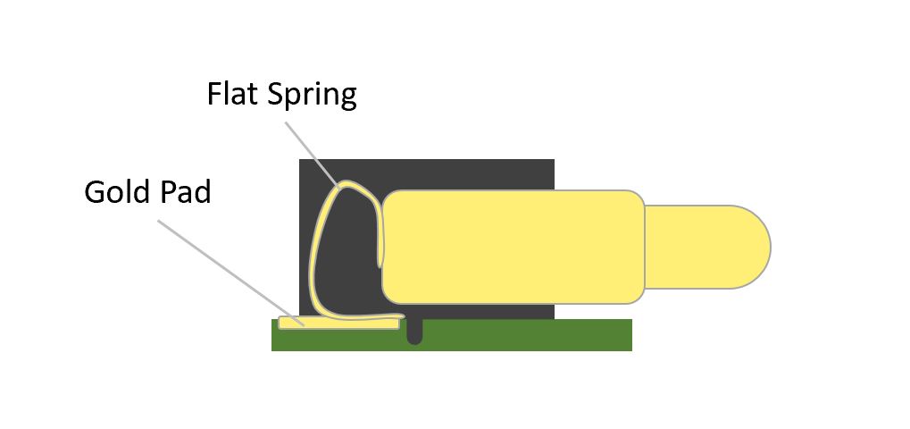
Another way to mount a pogo pin on a PCB is to attach a flat spring to the end of the pin. The connector can then be fixed in the housing or via mounting legs on the PCB, as shown above. This option is commonly used for right-angle pins.
Option 7: How to mount double-ended pogo pins?
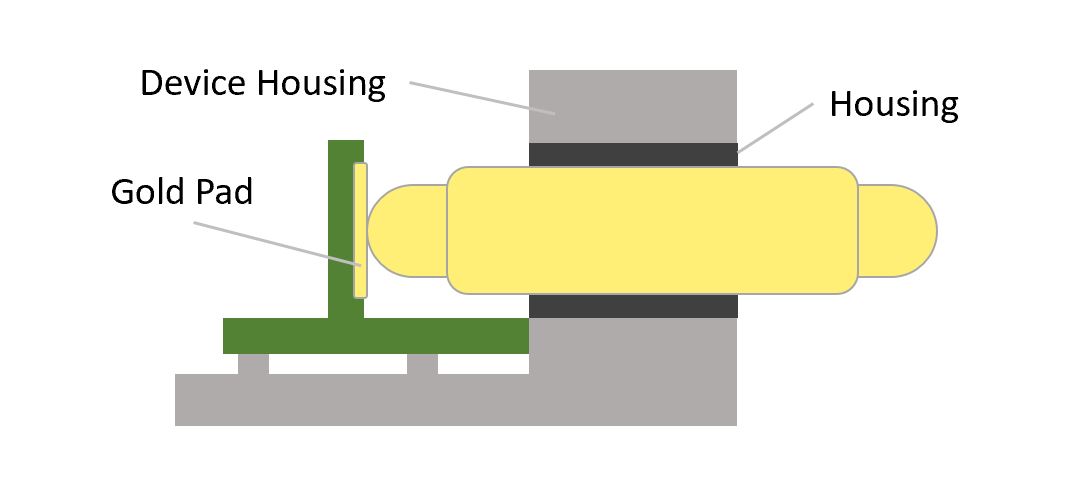
One elegant way to mount a pogo pin is to simply use a double-ended pin. This allows very simple and efficient assembly. The pin can either be press-fitted directly into the device housing, or mounted in a plastic housing that is in turn attached to the device. The picture above shows the latter version.
Need help choosing a mounting option?
Learn more in our introduction to pogo pins, find a part number in the pogo pin search, or contact us for advice on mounting pogo pins in your design.